Nov 2013 - CHG 1
2.3 Field-of-View
FAA Regulatory and Guidance Material
· Each flight, navigation, and powerplant instrument for use by any pilot must be plainly visible to him from his station with the minimum practicable deviation from his normal position and line of vision when he is looking forward along the flight path. [14 CFR 25.1321(a)]
See also: 14 CFR 23.1321(a), 27.1321(a), and 29.1321(a) which are worded slightly differently.
· The instruments should be arranged for use by any pilot and must be readily visible to the pilot. Instrument location and arrangement, with respect to the pilot’s seat, should be designed to accommodate pilots from 5’2” to 6’0” in height. Pilots within this range should be able to see and, where necessary, reach and operate all of the displays. [AC 27-1B, AC 27.1321; AC 29-2C, AC 29.1321a]
· All displays shall be fully readable up to a horizontal viewing angle of 35 degrees from normal to the face of the display screen. [TSO-C146c/RTCA DO-229D, 2.2.1.1.4.3]
· They shall be fully readable up to a vertical viewing angle of 20 degrees from normal to the face of the display screen. [TSO-C146c/RTCA DO-229D, 2.2.1.1.4.3]
· This angle of regard does not ensure that the equipment may be installed in any aircraft; it is recommended that the angle of regard be maximized to increase the flexibility of the equipment for installation. [TSO-C146c/RTCA DO-229D, 2.2.1.1.4.3]
· If the aircraft is flying a vertical path (for example, VNAV path), then the deviation from that path should be displayed in the primary field of view, such as the PFD, navigation display (ND), or other acceptable display. [AC 25.1329-1B, 64.i(1)(b)]
· All indicating means displayed (indicia, pointers, symbols, etc.) shall be completely visible from any eye position within the viewing envelope(s) as specified by the equipment manufacturer. Text and symbology shall be readily discernible and should be legible and readable within the specified viewing envelope(s). [TSO-C113a/SAE AS8034B, 4.2.1]
Note: It is the responsibility of the equipment installer to determine that the required aircraft viewing envelope is within the specified display viewing envelope(s). [TSO-C113a/SAE AS8034B, 4.2.1]
· The size of the viewing envelope should provide visibility of the flight deck displays over the flightcrew’s normal range of head motion, and support cross-flight deck viewing if necessary. [AC 25-11A, 16.a(12)]
· Displays should be located such that the pilot(s) can monitor them with minimal head and eye movement between displays. Flight information should be legible, accurate, easily interpreted, sufficiently free of visual cutoff (viewing angle), parallax and distortion, for the pilot to correctly interpret it. [AC 23.1311-1C, 14.1]
· The applicable flightcrew members, seated at their stations and using normal head movement, must be able to see and read display format features such as fonts, symbols, icons and markings so they can safely perform their tasks. In some cases, cross-flight-deck readability may be required to meet the intended function (§ 25.1301(a)) that both pilots must be able to access and read the display. [AC 25.1302-1, 5-5.b(2)]
See also: AMC 25.1302, 5.4.2.c which is worded slightly differently; Chapter 3.4 Markings, Dials, Tapes, and Numeric Readouts; Chapter 8 Intended Function
· Readability must be maintained in sunlight viewing conditions per § 25.773(a) and under other adverse conditions such as vibration and turbulence. Figures and letters should not extend below the visual angles defined in SAE ARP 4102-7 at the design eye position of the flight crewmember who normally uses the information. [AC 25.1302-1, 5-5.b(2)]
See also: AMC 25.1302, 5.4.2.c which is worded slightly differently.
· Analysis of the angular offset of a display from the pilot’s centerline of vision may be necessary to determine how accessible that display is in a visual scan. Additionally, the visual angle subtended by the display may be used to determine how readable the display will be (apparent display size). Final assessment of the acceptability of the visibility of the instruments will require a geometrically correct mockup or the actual airplane. [PS-ACE100-2001-004, Appendix A]
· Line widths shall be of sufficient size and optimal sharpness to display the intended information with no distracting visual artifacts or ambiguities that could result in an unsafe condition. When viewed from within the design eye position viewing envelope (DEP-VE), lines of a specified color and luminance should appear uniform in width at all rotational or translational orientations of the line. Line width variation should not be readily apparent. Narrow or thin lines with a minimum line width less than 70% of the maximum line width, of that particular line, may produce an undesirable visual “roping” effect. [TSO-C113a/SAE AS8034B, 4.2.5]
· The design eye position is a single point selected by the applicant that meets the requirements of §§ 25.773(d) and 25.777(c) for each pilot station. Figure 1 depicts a design eye position and pilot compartment view for optimum collision avoidance potential for the left pilot seat. For the right pilot seat, all left/right dimensions are reversed. [AC 25.773-1, 4.b.]
· Position of displayed information: Distance from the design eye position (DEP) is generally used. If cross-flight deck viewing of the information is needed, distance from the offside design eye position (DEP), accounting for normal head movement, should be used. For displays not mounted on the front panel, the distance determination should include any expected movement away from the DEP by the flightcrew. [AC 25-11A, 31.a(2)]
Alerts and Annunciations
See also: Chapter 4.1 Considerations for Alerting: General
· In most applications, critical information that is considered to be essential for safe flight, with warning or cautionary information that requires immediate pilot action or awareness, should be placed in the primary field-of-view. [AC 23.1311-1C, 15.2]
· Some annunciations may be acceptable within 35 degrees if they are associated with a unique aural tone or a master warning/caution annunciations that is within 15 degrees and with a pilot evaluation. [AC 23.1311-1C, 15.4, Note 4]
· Annunciations and indications should be consistently located in a specific area of the electronic display. Annunciations that may require immediate flightcrew awareness should be located in the flightcrew’s forward/primary field of view. [AC 25-11A, 31.f(2)]
See also: AC 23.1311-1C, 18.1 which is worded slightly differently.
· The visual-alert information should be located so that both pilots are able to readily identify the alert condition. [AC 25.1322-1, Appendix 1, 2.a(2)]
· The horizontal (and vertical) deviation(s) display(s) and failure annunciations should be located within the pilot's primary field of view, as should any indication requiring immediate aircrew action. [AC 20-138C, 11-8.b(4)]
See also: AC 25-11A, 31.f(2) and AC 23.1311-1C, 18.1 which are worded slightly differently; Chapter 4 Considerations for Alerting
· Displays used for waypoint sequencing, start of a turn, turn anticipation, active waypoint, distance to active waypoint, desired track and actual track (track angle error), and automatic mode switching should be located within the pilot’s primary field of view, or on a readily accessible display page. [AC 20-138C, 14-2.b]
See also: Chapter 2.2 Display Installation and Integration
· Displays used for loss of integrity monitoring, TO/FROM indication, and approach mode annunciation should be located within the pilot’s primary field of view. [AC 20-138C, 14-2.b(1)]
See also: Chapter 2.2 Display Installation and Integration
· Traditionally, 14 CFR part 23 airplanes with “classic” analog instrumentation in the “basic T” arrangement have included the center radio stack within the allowable field of view to satisfy this guidance. There is no intent for this AC to change that long-standing guidance. [AC 20-138C, 14-2.b(2)]
· The alerting elements for time-critical warnings should include: [AC 25.1322-1, 6.b]
- Unique voice information or unique tone, or both, for each alerting condition, and
- Unique visual alert information in each pilot’s primary field of view for each alerting condition.
· For example, unique visual alert information presented in each pilot’s primary field of view is acceptable in place of a master visual alert if it provides immediate awareness and sufficient attention-getting characteristics. [AC 25.1322-1, 6.c]
· Master visual alerts for warnings (master warning) and cautions (master caution) should be located in each pilot’s primary field of view. [AC 25.1322-1, Appendix 1, 1.a]
· To determine the quantity of displays that provide warning, caution, and advisory alerts, take into account the combination of ergonomic, operational, and reliability criteria, as well as any physical space constraints in the flight deck. [AC 25.1322-1, Appendix 1, 2.a(1)]
· All warning and caution visual information linked to a master visual alert should be grouped together on a single dedicated display area. There may be a separate area for each pilot. Advisory alerts should be presented on the same display area as warning and caution information. The intent is to provide an intuitive and consistent location for the display of information. [AC 25.1322-1, Appendix 1, 2.a(3)]
· Time-Critical warning visual information should appear in each pilot’s primary field of view. [AC 25.1322-1, Appendix 1, 3.a]
Note: The primary flight display (PFD) is used as a practical and preferred display for displaying the time-critical warning alerts since the pilot constantly scans the PFD. Integrating time-critical information into the PFD depends on the exact nature of the warning. For example, a dedicated location on the PFD may be used both as an attention-getting function and a visual information display by displaying alerts such as “WINDSHEAR,” “SINK RATE,” “PULL UP,” “TERRAIN AHEAD,” and “CLIMB, CLIMB.” In addition, graphic displays of target pitch attitudes for Airborne Alert and Collision Avoidance System (ACAS) II Resolution Advisories and Terrain may also be included. [AC 25.1322-1, Appendix 1, 3.a]
· Information for error detection may …[be] indications provided to the flightcrew during normal monitoring tasks… Indications on instruments in the primary field of view used during normal operation may be adequate if the indications themselves contain information used on a regular basis and are provided in a readily accessible form. These may include mode annunciations and normal airplane state information such as altitude or heading. Other locations for the information may be appropriate depending on the flightcrew’s tasks, such as on the control-display unit when the task involves dealing with a flight plan. [AC 25.1302-1, 5-7.b.]
See also: AMC 25.1302, 5.6.2 which is worded slightly differently; Chapter 8 Intended Function
Information to be Displayed in the Primary Field-of-View
· Required engine indications necessary to set and monitor engine thrust or power should be continuously displayed in the flightcrew’s primary field of view, unless the applicant can demonstrate that this is not necessary. The automatically selected display of powerplant information should not suppress other information that requires flightcrew awareness. [AC 25-11A, 36.b(4)(a)]
See also: Chapter 5.1 Basic “T” Arrangement
· The primary flight display of FPV/FPA symbology must not interfere with the display of attitude and there must always be attitude symbology at the top center of the pilot's primary field of view, as required by § 25.1321. [AC 25-11A, Appendix 1, 4]
· AC 23.1311-1C, Table 3 provides examples of information recommended for inclusion in this visual field. [See Examples section]
Required Navigation Performance (RNP) Approach - Performance and Functional Requirements
· A non-numeric lateral deviation display (for example, CDI, EHSI), with a TO/FROM indication and a failure annunciation, used as primary flight instruments for aircraft navigation, for maneuver anticipation, and for failure/status/integrity indication should have the following attributes: The display must be visible to the pilot and located in the primary field of view. [AC 20-138C, 8-3.g(3)(a)]
· To be approved as an alternative means, the navigation map display must be shown to meet the TSE requirements and be located in the primary field of view. [AC 20-138C, 8-3.g(3)(f)]
· The means to display the following items, either in the pilot’s primary field of view, or on a readily accessible display page: [AC 20-138C, 8-3.h(6)]
(a) Distance between flight plan waypoints
(b) Distance to go to the waypoint selected by the pilot
(c) Along track distances between waypoints
(d) Active navigation sensor type
(e) The identification of the active (To) waypoint
(f) The ground speed or time to the active (To) waypoint; and,
(g) The distance and bearing to the active (To) waypoint.
· The capability to display an indication of the RNP system failure in the pilot’s primary field of view. [AC 20-138C, 8-3.h(11)]
Required Navigation Performance (RNP) Terminal - System Performance Monitoring and Alerting
· A non-numeric lateral deviation display (for example, CDI, EHSI), with a TO/FROM indication and a failure annunciation, used as primary flight instruments for aircraft navigation, for maneuver anticipation, and for failure/status/integrity indication. [AC 20-138C, 9-3.g(2)]
· To be approved as an alternative means, the navigation map display must be shown to meet the TSE requirements and be located in the primary field of view. [AC 20-138C, 9.3.g(2)(f)]
· The means to display the following items, either in the pilot’s primary field of view, or on a readily accessible display page: [AC 20-138C, 9-3.h(6)]
(a) The active navigation sensor type
(b) The identification of the active (To) waypoint
(c) The distance and bearing to the active (To) waypoint; and
(d) The ground speed or time to the active (To) waypoint
· The capability to display an indication of the RNP 1 system failure in the pilot’s primary field of view. [AC 20-138C, 9-3.h(14)]
Barometric-Vertical Navigation (Baro-VNAV) Equipment Performance: Operations under IFR
· Systems that provide steering signals for FDs or autopilots should provide automatic vertical maneuver anticipation and a waypoint alert that occurs prior to the initiation of the vertical maneuver. Systems that are coupled to the automatic guidance/control system(s) should not cause the aircraft to depart an assigned altitude until the impending altitude change is indicated to the crew within the pilot’s primary field of view, then acknowledged by timely crew action. [AC 120-38C, 10-2.f(7)(a)]
General Human Factors Considerations
· Each display element, used as a primary flight instrument in the guidance and control of the aircraft, should be located where it is clearly visible to the pilot with the least practicable deviation from the pilot’s normal position and line of vision when looking forward along the flight path. (Note 2: FTE can be reduced when numeric display information is integrated with the non-numeric display or is located within the pilot’s primary field of view.) [AC 20-138C, 11-8.b(1)]
· The horizontal (and vertical) deviation(s), display(s), failure annunciations should be located within the pilot’s primary field of view, as should any indication requiring immediate aircrew action. [AC 20-138C, 11-8.b(4)]
Global Navigation Satellite Systems (GNSS)
· Displays used for waypoint sequencing, start of a turn, turn anticipation, active waypoint, distance to active waypoint, desired track and actual track (track angle error), and automatic mode switching should be located within the pilot’s primary field of view, or, on a readily accessible display page. [AC 20-138C, 14-2.b]
· Displays used for loss of integrity monitoring, TO/FROM indication, and approach mode annunciation should be located within the pilot’s primary field of view. [AC 20-138C, 14-2.b(1)]
· For installations containing more than one approach navigation source, the navigation source (for example, ILS, GPS/SBAS, baro-VNAV, etc.) selected for the approach must be positively indicated in the primary field of view. Consideration should be given to the overall aircraft-level annunciation philosophy. [AC 20-138C, 14-6.6.a.]
· The approach type (LP/LPV, LNAV/VNAV, LNAV) must be clearly annunciated to the pilot prior to and throughout the entire approach in the primary field of view. [AC 20-138C, 14-6.6.b]
· There must be an unambiguous indication the navigation source is provided by GPS/SBAS, GPS/GBAS, or ILS, as appropriate, in the primary field of view. [AC 20-138C, 14-6.6.b(1); 14-6.6.b(2)]
· For installations containing more than one approach navigation source, the navigation source (for example, ILS, GPS/GBAS, etc.) selected for the approach must be positively indicated in the primary field of view. [AC 20-138C, 14-8.8.a.]
· The approach type (GLS) must be clearly annunciated to the flight crew prior to and throughout the entire approach in the primary field of view (GLS). [AC 20-138C, 14-8.8.b]
· There must be an unambiguous indication the navigation source is provided by GPS/SBAS, GPS/GBAS, or ILS as appropriate in the primary field of view. [AC 20-138C, 14-8.8.b(1); 14-8.8.b(2)]
Area Navigation (RNAV) Multi-Sensor Equipment
· The distance to the active waypoint must be displayed either in the pilot’s primary field of view or on a readily accessible display page unless there are alternate means to indicate waypoint passage. [AC 20-138C, 15-2.1.b(1)]
· Multi-sensor equipment may drive remote annunciators in the primary field of view. [AC 20-138C, 15-3]
· Waypoint sequencing, start of a turn, turn anticipation, TO/FROM indication, approach mode annunciation, and automatic mode switching should be located within the pilot’s primary field of view, or, on a readily accessible display page. [AC 20-138C, 15-3.c]
· The multi-sensor equipment should provide annunciations for loss of integrity monitoring, loss of navigation, TO/FROM indication, and approach mode annunciation within the primary field of view. [AC 20-138C, 15-3.d]
Integration with GNSS-Provided Vertical Guidance
· There should be an annunciation in the primary field of view indicating the active approach type (for example, GLS, LPV, LP, LNAV/VNAV, LNAV). The intent is to ensure the crew has an unambiguous indication of the active approach in the primary field of view that will correlate to a line of minima on the approach chart. [AC 20-138C, 17-5.a.7]
Installation Considerations for RNP Authorization Required (AR)
· The aircraft manufacturer should also verify that a visual alert within the flight crew’s primary field of view occurs with a loss of navigation capability and/or loss of RNP containment integrity. An aural alert should accompany the visual alert. [AC 20-138C, Appendix 2, A2-8.b]
RNP Advanced Features
· The applicant should verify that a visible alert occurs within the flightcrew’s primary field of view when loss of navigation capability and/or loss of integrity are experienced. [AC 20-138C, Appendix 3, A3-2.a(5)]
· The instruments necessary for safe operation (e.g., airspeed indicator, gyroscopic direction indicator, gyroscopic bank‑and‑pitch indicator, slip‑skid indicator, altimeter, rate‑of‑climb indicator, master caution or warning (if installed), rotor tachometers, and the indicator most representative of engine power) should be installed immediately in front of pilots in their primary field of view (FOV). [AC 29.1321, b(1)]
· Display high priority information in the primary FOV as well as the primary flight information. [AC 29.1321, b(1)(i)]
Information to be Displayed in the Primary Optimum Field-of-View
Required Navigation Performance (RNP) Authorization Required (AR) General Requirements
· The aircraft should have an appropriately-scaled, non-numeric deviation display (i.e., lateral deviation indicator and vertical deviation indicator) in the pilot’s primary optimum field of view. [AC 20-138C, A2-3.d(1)(b)]
· In lieu of appropriately scaled lateral and vertical deviation indicators in the pilot’s primary optimum field of view, a numeric display of deviation may be acceptable depending on the flight crew workload and the numeric display characteristics. [AC 20-138C, A2-3.d(1)(c)]
· The navigation system must provide a display identifying the active waypoint either in the pilot’s primary optimum field of view, or on a readily accessible and visible display to the flight crew. [AC 20-138C, A2-3.d(2)]
· The navigation system must provide a display of distance and bearing to the active (TO) waypoint in the pilot’s primary optimum field of view. Where not viable, a readily accessible page on a control display unit, readily visible to the flight crew, may display the data. [AC 20-138C, A2-3.d(3)]
· The navigation system must provide the display of groundspeed and time to the active (TO) waypoint in the pilot’s primary optimum field of view. Where not viable, a readily accessible page on a control display unit, readily visible to the flight crew, may display the data. [AC 20-138C, A2-3.d(4)]
· The navigation system must provide a TO/FROM display in the pilot’s primary optimum field of view. [AC 20-138C, A2-3.d(5)]
· The navigation system must provide a display of the actual aircraft track (or track angle error) either in the pilot’s primary optimum field of view or on a readily accessible and visible display to the flight crew. [AC 20-138C, A2-3.d(7)]
· The aircraft must provide a means to annunciate failures of any aircraft component of the RNAV system, including the navigation sensors. The annunciation must be visible to the pilot and located in the primary optimum field of view. [AC 20-138C, A2-3.d(8)]
· The aircraft must display barometric altitude from two independent altimetry sources, one in each pilots’ primary optimum field of view to support an operational cross check of altitude sources. (Note 1: If the aircraft includes the ability to automatically compare the output of the independent altitude sources, including independent aircraft static air pressure systems, and the aircraft can provide an alert in the pilot’s primary optimum field of view when deviations between the sources exceed +/-100 feet, then the applicant should document this comparator monitoring function in the AFM/RFM or aircraft qualification guidance.) [AC 20-138C, A2-3.d(14)]
· The aircraft must display the current navigation sensor(s) in use. The aircraft should provide this display in the primary optimum field of view. [AC 20-138C, A2-3.d(15)]
Reversionary Flight Displays Instead of Standby Instruments or Dual PFDs
· The PFI should be presented in similar format and sufficient size in the reversionary mode as it is in normal mode to allow the pilot to enhance the control of the airplane. This reversionary configuration should provide backup information essential to continued safe flight and landing with an intuitive control that allows instant, simultaneous access to reversionary mode on both the PFD and MFD displays. The single pilot action should be easily recognized, readily accessible, and have
the control within the pilot’s primary optimum field of view. An acceptable method for the single pilot action is the red color and/or lighted red “halo” ring that announces its position on the panel at all times. [AC 23.1311-1C, 8.4.1.d]
· If an aircraft is equipped with multiple AHRS, it may be acceptable, when one AHRS fails, to drive both the autopilot and the PFD from a single AHRS as long as an AHRS independent attitude display (required for some aircraft classes) is located in the primary maximum field of view. [AC 23.1311-1C, 8.3.2]
Information to be Displayed in the Secondary Field-of-View
· Signals and information pilots scan as part of monitoring the aircraft and its performance are located in the secondary FOV. The secondary FOV is bound laterally to minimize the need for pilots to turn their heads to view the information. Examples of information typically located in the secondary FOV are: [AC 29.1321, b(1)(ii)]
(A) Ancillary navigation information (moving maps, weather displays, etc).
(B) Secondary powerplant information like engine oil pressures and temperatures.
(C) Caution advisory and warning system (CAWS) panel (if a master caution or warning indicator is located in the primary FOV, otherwise the CAWS panel should be as close to the pilots primary FOV as possible).
(D) Autopilot.
(E) Navigation controls.
· Nonprecipitation Conditions. [AC 29-2C, AC 29.773a]
(1) Explanation.
(i) The procedures paragraph following this explanation discusses one means of demonstrating an adequate field of view.
(ii) Since glare and reflection often differ with the sun’s inclination, consideration should be given to evaluating the cockpit at midday and in early morning or late afternoon. Windshields with embedded wire heating elements should be evaluated for distortion with the system both “ON” and “OFF.”
(iii) If night approval is requested, all lighting, both internal and external, should be evaluated in likely combinations and under expected flight conditions. Although a certain amount of equipment reflection (avionics control heads, etc.) in the windscreen may be unavoidable, the pilot’s normal field of view should be unobstructed. Windshield reflections often dictate large glareshields which result in reduction of the optimum field of view. This problem is most apparent in IFR equipped aircraft (having larger instrument panels and avionic consoles) which are operated in VFR utility roles. Landing and taxi lights should be exercised throughout their adjustment range (if applicable) to check for reflections, particularly in chin windows. Anticollision and strobe lights should be evaluated to ensure that frequency interaction and reflections off the rotor do not result in distractions to the pilot. The effect of cabin lighting on the pilot compartment view should be assessed, particularly on EMS configured aircraft where the in-flight use of cabin lights may be mandatory.
(2) Procedures. The following procedures are one acceptable means of evaluating pilot compartment field of view considering only those objects in the pilot compartment, the windshield, and its support structure in nonprecipitating conditions. The applicant’s design is not required to meet these guidelines, and each design should be evaluated on its own merits.
The area of visibility established in the following paragraphs will provide an acceptable level of visibility for a minimum crew of one (pilot). In the event that a minimum crew of two (pilot and copilot) is required, the second pilot should have an area of visibility equivalent to that provided for the pilot but on the opposite side. In this event, the pilot’s area of visibility to the left as shown in figure AC 29.733-1 needs only to comply to 60° left, and the area of visibility for the second pilot needs only to comply to 60° right.
(i) A single point established in accordance with the provisions of this paragraph constitutes the referenced eye position (i.e., a point midway between the two eyes) from which the central axis may be located. The referenced eye position is a reference datum point based on the eye location that permits the specified vision envelope required by figure AC 29.733-1, allows for posture slouch, and is the datum point from which the aircrew station geometry is constructed. The referenced eye position should be located by means of ship’s coordinates that contain station reference number, water line, and butt line for both pilot and copilot, if applicable, and complies with:
(A) The pilot’s seat in a normal operating position from which all controls can be utilized to their full travel, by an average subject, and which should provide for vertical adjustment of the seat of not less than 2.5 inches above and 2.5 inches below this initial vertical position.
(B) The seat back in its most upright position.
(C) The seat cushion depression being that caused by a subject weighing 170 to 200 pounds.
(D) The longitudinal axis of the rotorcraft to be that of “cruise attitude” (0.9VH or 0.9 VNE whichever is lower).
(E) The point established not beyond 1 inch to the right or left of the longitudinal centerline of the pilot’s seat.
(F) All measurements made from the single point established in accordance with this paragraph.
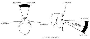
(ii) A dual lens camera, as photo recorder, should be used in measuring the angles specified in the paragraphs listed below. Other methods, including the use of a goniometer, are acceptable if they produce equivalent areas to those obtained with a dual lens camera. When not using a dual lens camera, compensation should be made for one-half the distance which exists between the eyes, or 1¼ inches. With the referenced eye position located as indicated in paragraph AC 29.733a(2)(i), and utilizing binocular vision and azimuthal movement of the head and eyes about a radius, the center of which is 3 and 5/16 inches behind the referenced position (this point to be known as the central axis), the pilot should have the following minimum areas of vision measured from the appropriate eye position. (See figure AC 29.733-1.)
(A) 20° forward and above the horizon between 0° and 100° left.
(B) 20° forward and below the horizon between 10° and 100° left.
(C) 20° forward and below the horizon at 10° left increasing to a point 30° forward and below the horizon at 10° right.
(D) 50° forward and below the horizon between 10° right and 135° right.
(E) 20° forward and above the horizon at 0° increasing to a point 40° above the horizon at 80° right and 100° right and then decreasing to a point 20° forward and above the horizon at 135° right.
(iii) Any vertical obstruction which falls within the minimum area of visibility outlined in paragraph AC 29.733a(2)(ii) should be governed by the following:
(A) No vertical obstruction between 20° right and 20° left.
(B) Between 20° right and 135° right, vertical obstruction should not exceed 2.5 inches in width.
(C) Between 20° left and 100° left no vertical obstruction greater than 2.5 inches in width.
(iv) Any horizontal obstruction which falls within the minimum area of visibility outlined in paragraph AC 29.733a(2)(ii) should be governed by the following:
(A) The area 15° forward and above the horizon between 135° right and 40° left decreasing to a point 10° above the horizon at 100° left, and 15° forward and below the horizon between 135° right and 100° left should be free from horizontal obstructions.
(B) The area above and below the horizon which is between the minimum area of vision specified in paragraph AC 29.733a(2)(ii) and paragraph AC 29.733a(2)(iv)(A) is limited to one horizontal obstruction above the horizon, and one below the horizon. These horizontal obstructions should not be greater than 4 inches in width. An overhead window which will provide twice as much additional visibility as was lost due to the obstruction, should be located immediately above any obstruction which is above the horizon. This requirement is in addition to any area of visibility specified by paragraph AC 29.733a(2)(ii) which may be included in the overhead window area.
(C) If the instrument panel obstructs any required area between 10° left and 10° right below 20° forward and below the horizon, a window which affords triple equivalent additional visibility should be located immediately below and between the angles of 20° left and 20° right above 65° below the horizon.
(v) For steep rejected takeoffs and steep approaches such as used for oil rigs or confined heliports, the visibility should be such that the pilot can see the touchdown pad and sufficient additional area to the side and forward to provide both an accurate approach to the touchdown point as well as a satisfactory degree of depth perception. A 5-inch head movement, by the pilot, forward and/or sideward of the normal position is acceptable in determining compliance.
· Precipitation Conditions [AC 29-2C, AC 29.773b]
(1) Explanation.
(i) Heavy rainfall is defined by the National Weather Service as one resulting in accumulation in excess of 0.03 inches in 6 minutes. On past designs, the windshield wipers required by § 29.1307 have been adequate to ensure satisfactory view at low to medium airspeeds. Airflow over the windshield and/or wipers has normally been sufficient to keep the windshield clear at higher airspeeds. Obscuration of side windows by rainfall should be addressed, particularly for confined area approaches.
(ii) If icing certification is requested, a means must be provided to ensure that a sufficiently large viewing area is kept clear of ice to permit safe operation. As a minimum, a clear area on the windshield should be available, although some configurations could require clear view in other areas, in order to provide an adequate level of safety in certain operations.
(iii) An openable “clear view” window must be provided for the first pilot. The rule requires that the window be openable in heavy rain at forward speeds to VH and in the worst icing conditions requested for certification. The rule further requires a field of view through this opening which is adequate for safe operation. Although the rule implies that a safe field of view must be provided for airspeeds up to VH, it has not been interpreted as such. In most designs, the only practical location for an openable window is in a side panel or door. Aircraft sideslip limits normally restrict useful view from this window opening at high airspeeds. The intent is to provide the pilot with an adequate view for safe approach and landing in the event that normal windshield clearing systems malfunction.
(2) Procedures. Compliance with the requirements of this rule should be checked by flying the aircraft in the applicable environmental conditions. Although wipers can be partially checked on the ground with a hose, their effectiveness at higher airspeeds should also be verified. Likewise, additional or alternate rain removal systems should be exercised throughout the required airspeed range. The need for windshield wash systems should be assessed, particularly if the aircraft will be used in an offshore salt spray environment. Systems provided to ensure clear view in icing conditions should be evaluated during icing flight tests. The location and effectiveness of the openable window should be evaluated following failure of the rain removal and anti-ice system (if applicable). The view through the window opening should permit safe operation from hover up to a reasonable approach airspeed. Care should be exercised during flight test to stay within airframe sideslip limits.
· The nominal viewing distance should be 29 in (737 mm) from the pilot’s design eye point. Critical displays in the pilot’s field-of-view should have a minimum viewing distance of 10 in (254 mm); less critical displays may have a minimum viewing distance of 13 in (330 mm). The maximum viewing distance should be 40 in (1,016 mm). (McAnulty, 1995)
· All indicating means (indicia, pointers, symbols, etc.) on the useful display surface shall be completely visible from any eye position within the instrument's viewing envelope as specified by the equipment manufacturer. Each installation should be examined to insure that the design eye position is within the instrument's viewing envelope. The examination may be a combination of test, analysis, simulation or flight test. [SAE ARP1874, 5.1.2]
Alerts and Annunciations
· Visual alerts shall be presented in a consistent location in the forward field of view. [RTCA DO-256, 2.1.6]
· High priority alarms should be placed in the pilot’s primary field-of-view. If all critical alerts cannot be placed within 15 degrees, a master warning display is also appropriate. [GAMA Publication No. 10, 7.1.5.1]
· Visual warnings must be placed in the primary field-of-view. [GAMA Publication No. 10, 7.1.7.1]
· A visual enunciation of warnings and cautions should be displayed within the pilot’s primary field of view, always located in the same position on a manufacturer’s product. Separate and discrete enunciators for warnings and cautions should be integrated into a single display. If the CAS does not present required warnings or cautions in the pilot’s primary field of view, a master warning/caution annunciation (aural and visual, if applicable) shall be provided. Visual indication of master warning/caution shall be located within the pilot’s primary field of view. [GAMA Publication No. 12, 11.1]
Information to be Displayed in the Primary Field-of-View
· Critical or frequently used displays shall be located in the central visual field… and occupy a privileged position in that field (e.g., the top or left-most position). [Ahlstrom and Longo, 2003, 5.1.2.10]
· Indicators for critical functions shall be located within 15° of the user's normal line of sight [Ahlstrom and Longo, 2003, 6.2.2.1.8]
· Displays used most frequently shall be grouped together and placed in the optimum visual zone. [MIL-STD-1472G, 5.2.2.2.5.b]
· For critical functions as defined by the task analysis, indicators shall be located within 15 degrees of the user’s normal line of sight. Warning lights shall be an integral part of, or located adjacent to, the lever, switch, or other control by which the user is to take action. [MIL-STD-1472G, 5.2.3.13.11]
· Hardware input controls should be placed in the cockpit and arranged in a consistent manner to allow ease of use by the pilot. The criticality of the function being controlled must also be considered in determining the position of the control in the cockpit/flight deck. The location of navigation controls becomes very important if the navigation systems are used during critical phases of flight…Functions that need to be used in higher workload phases of flight, e.g. approach, need to be located in the primary FOV. [GAMA Publication No. 10, 7.1.2.5]
· By examination or analysis, determine that navigation system inputs and navigation display parameters of commands and path deviation are located in the primary field-of-view. Other non-flight critical navigation information may be displayed in secondary-field-of-view. For example, a CDU that is not the sole or primary device being used to display dynamic position data used directly to fly the aircraft to maintain a navigation path may be in the secondary field-of-view, pedestal or side console areas and may display such data itself. [GAMA Publication No. 10, 7.1.4.6]
· Critical functions will be in the pilot’s primary field-of-view with longitudinal awareness, lateral/vertical awareness and height awareness display symbols on horizontal line in front of the pilot using the information. [GAMA Publication No. 10, 7.1.4.7]
· Validate that attitude, altitude, airspeed and basic level of navigation (including heading) is within the pilot’s primary field-of-view (FOV) as determined through visual field modeling in a three-dimensional electronic cockpit mockup, measurement in a development fixture or other mockup, or measurement on engineering drawings. Regardless of the specific implementation or parameter used, critical data and information should be displayed in the primary FOV. [GAMA Publication No. 10, 7.1.4.7]
· By examination or analysis determine that critical reversionary display functions are in the pilot’s primary or secondary field-of-view from that pilot position. [GAMA Publication No. 10, 7.1.4.8]
· At a minimum, the primary navigation information must be in the primary field of view and shall include: [GAMA Publication No. 12, 6.1.2.1]
6.1.2.1.1 A Horizontal Situation Indicator (HSI). The HSI shall be capable of displaying vertical deviation and a digital distance indication to/from the selected fix. The HSI should provide arc and/or 360° moving-map modes. (Reference RTCA DO-257*)
6.1.2.1.2 ‘TO’ and ‘FROM’ Indication. The TO indication will be situated between the airplane symbol and the head of the course indicator. The FROM indication will be situated between the airplane symbol and the tail of the course indicator. The TO/FROM indication should be visible in both a 360° mode and an arc display.
6.1.2.1.3 Display Status. The approach, terminal, enroute, Course Deviation Indicator (CDI) scale or RNP status when displayed as prescribed by DO-229C shall be in the same location on a supplier’s product, labeled with the correct abbreviation. (Reference RTCA DO-229C*)
6.1.2.1.4 Course Deviation Indicator. When CDI scaling value is displayed, it shall be in nautical miles and the indication shall be adjacent to the CDI.
6.1.2.1.5 Display of Navigation Sources. The navigation source commanding the lateral deviation bar or bearing indicators shall be labeled in a prominent and unambiguous manner and located adjacent to the HSI. This information will be provided to the pilot in the same location on a supplier’s product, using the correct abbreviations. (Reference 14 CFR parts 23.1329, 23.1335, 23.1311).
6.1.2.1.5.1 Navigation-Source Labels. If installed, the following labels should be used to indicate navigation sources:
VOR1, VOR2
ADF1, ADF2
LOC1, LOC2
GPS1, GPS2
FMS1, FMS2
LRN1, LRN2
NAV1, NAV2
· When any portion or axis of the autopilot system is engaged to the airplane flight controls, an annunciation that the autopilot is engaged must always be displayed in the pilot’s primary field of view. [GAMA Publication No. 12, A.3.2.1]
· High priority alarms should be placed in the pilot’s primary field-of-view. If all critical alerts cannot be placed within 15 degrees, a master warning display is also appropriate. [GAMA Publication No. 10, 7.1.5.1]
· The most critical displays and their controls are located in the primary field-of-view. [GAMA Publication No. 10, 7.1.7.1]
Information to be Displayed in the Secondary Field-of-View
· Under failure conditions reversionary data in the Basic-T may be in the pilot’s secondary field-of-view. [GAMA Publication No. 10, 7.1.4.8]
· The next most critical displays and their controls are located in the secondary field-of-view. [GAMA Publication No. 10, 7.1.7.1]
· Current surface trim position indication may be displayed to the pilot in the secondary field-of-view. [GAMA Publication No. 10, 7.1.8.2]
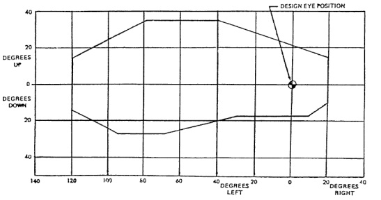
A variety of terms are used in regulatory and guidance material to refer to the “primary field-of-view”, including “primary field-of-view”, “primary optimum field-of-view”, and “primary maximum field-of-view”. The FAA is moving towards use of the term “primary field-of-view”. A list of terms currently used and the definitions provided from FAA regulatory and guidance material are included in Table 2.3.1 in the Examples section. FAA regulatory and guidance material generally bases the pilot’s primary field-of-view on “the optimum vertical and horizontal visual fields from the design eye reference point that can be accommodated with eye rotation only. With the normal line-of-sight established at 15 degrees below the horizontal plane, the values for the vertical (relative to normal line-of-sight forward of the aircraft) are +/-15 degrees optimum, with +40 degrees up and -20 degrees down maximum. For the horizontal visual field (relative to normal line-of-sight forward of the aircraft), the values are +/-15 degrees optimum, and +/-35 degrees maximum.” (See AC 25.1322-1.) This region is depicted below.

Figure 1. Primary Field-of-View. Image excerpted from AC 25.1322-1, Appendix 5.
The description of primary field-of-view used in human factors research reports generally define it as a region with a 15 degree radius extending from the normal line of sight; the normal line of sight is established as 15 degrees below a line extending horizontally from the eye (e.g., Ahlstrom and Longo, 2003; Cardosi and Huntley, 1993; Cardosi and Murphy, 1995; MIL-STD-1472G). Some documents also refer to this region as the primary optimum field-of-view and describe a primary maximum field-of-view that is +/-35 degrees horizontal, and +40 degrees up and -20 degrees down. This description is identical to that used in FAA regulatory and guidance material and depicted in Figure 1 Primary Field-of-View (Ahlstrom and Longo, 2003; MIL-STD-1472G). Finally, other documents define a region within 30 degrees of the normal line of sight and allow caution signals or other secondary signals to be presented within that region (Veitengruber, 1979). A list of definitions excerpted from key human factors research reports are presented in Table 2.3.2 in the Examples section.
The regions that comprise the primary field-of-view correspond to the area of the visual field with the highest visual acuity. This is the part of the eye with the highest density of visual receptor cells and thus, the best visual acuity and detailed vision. (The density of receptor cells decreases from the center of the eye towards the periphery, so visual acuity decreases correspondingly as well.) Information placed outside the primary field-of-view may not be detected as quickly. Thus, critical information considered necessary for safe flight or that requires immediate pilot action or awareness is generally presented in this central location (Boucek, Veitengruber, and Smith, 1977; Cardosi and Huntley, 1993; Cardosi and Murphy, 1995; Veitengruber, Boucek, and Smith, 1977).
The distance from the design eye position (DEP) is typically used to evaluate the visibility and readability of information on the flight deck. AC 25-11A defines the DEP as:
“the position at each pilot's station from which a seated pilot achieves the required combination of outside visibility and instrument scan. The DEP is a single point selected by the applicant that meets the requirements of §§ 25.773(d), 25.777(c), and 25.1321 for each pilot station. It is normally a point fixed in relation to the aircraft structure (neutral seat reference point) at which the midpoint of the pilot's eyes should be located when seated at the normal position. The DEP is the principal dimensional reference point for the location of flight deck panels, controls, displays, and external vision” (see AC 25-11A, Appendix 3).
AC 25-11A contains a requirement for measuring viewing distance to flight deck instruments using the DEP (see AC 25-11A, Section 31.a(2)). However, AC 23.1311-1C notes that “Part 23 rules do not require the applicant to establish a cockpit design eye reference point from which to measure viewing distances and angular displacement to various cockpit equipments” [AC 23.1311-1C, 15.1]. If an applicant intends to seek display approval for a specific system across for multiple types of aircraft (e.g., parts 23, 25, 27, 29), it may be worthwhile for that applicant to comply with to the most stringent requirements for any given regulation or related regulatory and guidance material, which in this case would be the part 25 guidance.
The flight deck of some rotorcraft may not allow for the same types of display configurations as on fixed wing aircraft. Specifically, AC 29-2C, Certification of Transport Category Rotorcraft, provides different field-of-view requirements from those specified for aircraft to accommodate a wider range of flight deck designs (note that AC 27-1B (Change 3), Certification of Normal Category Rotorcraft, contains related policy, which is worded differently). Thus, text excerpted from AC 29-2C, AC 29.773, is provided to detail the field-of-view requirements for transport category rotorcraft.
Alerts located on displays outside the pilot’s primary field-of-view may be missed. In an examination of problems associated with the use of LORAN-C/GPS receivers, pilots reported that they sometimes took up to four minutes to notice and respond to an alert, which may not have been indicated in the primary field-of-view. The alerts included red and yellow warning lights, blinking, and freezing the information on the display. Annunciator panels that display all the warning, caution, and advisory information on the flight deck can be used so that pilots can see at a glance which system malfunctioned or failed (Adams et al., 1993).
The following two tables list the terms and definitions used to refer to the primary field-of-view from FAA regulatory and guidance material (Table 2.3.1) and from human factors research reports and guidance documents (Table 2.3.2).
Table 2.3.1. Primary field-of-view. The definitions were excerpted from the source material.
|
FAA Regulatory and Guidance Material |
Term |
Definition (Excerpted from FAA Regulatory and Guidance Material) |
|---|---|---|
|
AC 20-138C, Airworthiness Approval of Positioning and Navigation Systems |
Primary field of view
|
The vertical and horizontal visual fields relative to the design eye reference point that can be viewed with eye rotation only using foveal or central vision. The values for the horizontal (relative to the normal line of sight) are +/-15 degrees optimum, with +/- 35 degrees maximum. The values for the vertical (relative to normal line of sight) are +/-15 degrees optimum, with + 40 degrees up and -20 degrees down maximum (see AC 25-11 latest revision). The primary field of view definition should be broad enough to include the center radio stack on 14 CFR part 23 airplanes with “classic”, analog basic ‘T’ instrumentation. For rotorcraft, reference the visibility requirements defined in the latest revisions of AC 27-1 and 29-2. [Appendix 7-1.r.] |
|
Primary Optimum Field of View |
For the purpose of this AC related to RNP AR, the primary optimum field of view is within +/-15 degrees horizontal and vertical relative to the pilot’s normal line of sight. [Appendix 7-1.s.] |
|
|
AC 23.1311-1C, Installation of Electronic Display in Part 23 Airplanes |
Field-of-view |
The angular extent of the display that can be seen by either pilot with the pilot seated at the pilot’s station. [6.2.p] Part 23 rules do not require the applicant to establish a cockpit design eye reference point from which to measure viewing distances and angular displacement to various cockpit equipments. [15.1] |
|
Primary optimum field-of-view
|
Primary optimum field-of-view is based on the vertical and horizontal visual fields from the design eye reference point that can be accommodated with eye rotation only. With the normal line-of-sight established at 15 degrees below the horizontal plane, the values for the vertical and horizontal (relative to normal line-of-sight forward of the aircraft) are +/-15 degrees. This area is normally reserved for primary flight information and high priority alerts. [15.2] Image in Figure 1 included. |
|
|
Primary maximum field-of-view |
Primary maximum field-of-view is based on the vertical and horizontal visual fields from the design eye reference point that can be accommodated with eye rotation and minimal head rotation. These values are +/-35 degrees horizontal, and +40 degrees up and -20 degrees down vertical. These areas are normally used for important and frequently used information. A pilot’s visual scan and head rotation is minimized when information is placed in this area. Placement of information in this area also reduces the potential for spatial disorientation. [15.3] Image in Figure 1 included. |
|
|
AC 25-11A, Electronic Flight Deck Displays |
Primary field of view |
Primary Field-of-View is based on the optimum vertical and horizontal visual fields from the design eye reference point that can be viewed with eye rotation only using foveal or central vision. The description below provides an example of how this may apply to head-down displays. With the normal line-of-sight established at 15 degrees below the horizontal plane, the values for the vertical (relative to normal line-of-sight forward of the aircraft) are +/-15 degrees optimum, with +40 degrees up and -20 degrees down maximum. [A3-9] Image in Figure 1 included. |
|
AC 25.1322-1, Flightcrew Alerting |
Primary field of view |
Primary Field of View is based upon the optimum vertical and horizontal visual fields from the design eye reference point that can be accommodated with eye rotation only. The description below provides an example of how this may apply to head-down displays. With the normal line-of-sight established at 15 degrees below the horizontal plane, the values for the vertical (relative to normal line-of-sight forward of the aircraft) are +/-15 degrees optimum, with +40 degrees up and -20 degrees down maximum. For the horizontal visual field (relative to normal line-of-sight forward of the aircraft), the values are +/-15 degrees optimum, and +/-35 degrees maximum. [Appendix 5] Image in Figure 1 included. |
Table 2.3.2. Field-of-view terms as defined and/or used in human factors research reports and guidance documents.
|
Document |
Term |
Definition (Excerpted from Document) |
|---|---|---|
|
Human Factors Design Standard (Ahlstrom and Longo, 2003) |
Optimum vertical and horizontal visual fields
|
The following figures are used to define the optimum vertical and horizontal visual fields. No text definition is provided.
---------------------------------------------------------------------------- [See Section 5.1.2.10 or Section 6.2.2.1.8] |
|
Central visual field |
Central visual field (sometimes referred to as the focal area) is the central 30° of the visual field. This is the area that people use to look at objects in the world, moving their eyes as needed to bring images of the object onto the fovea, which is the area of highest acuity. When an object is outside of the focal area, a person will usually turn their head rather than simply move their eyes. [5.1.2.10] |
|
|
Human Factors for Flight Deck Certification Personnel (Cardosi and Huntley, 1993) |
N/A |
As a practical matter, one can now see why FAA guidelines stress the importance of placing master visual alerts within 15º of each pilot’s normal line of sight as illustrated [in the figure below]. This is the area of the visual field with best visual acuity and typically the center of attention. [Page 21] |
|
Human Factors in the Design and Evaluation of Air Traffic Control Systems (Cardosi and Murphy, 1995) |
N/A |
This optimal area can be thought of as a cone extending from the normal line of sight with a radius of 15 degrees. (The normal line of sight is the line 15 degrees below the line extending horizontally from the center of the pupil.) [7.2.11] |
|
MIL-STD-1472G |
Field-of-view |
The area that is visible for viewing only through eye and head movement. [3.3.13] |
|
Optimum visual zone |
The optimum vertical and horizontal visual fields are defined using the same figure shown in the Human Factors Design Standard. |
|
|
GAMA Publication No. 10, Recommended Practices and Guidelines for Part 23 Cockpit/Flight Deck Design, 2000 |
Primary Field-of-View |
Primary Field-of-View is based upon the optimum vertical and horizontal visual fields from the design eye reference point that can be accommodated with eye rotation only. With the normal line-of-sight established at 15 degrees below the horizontal plane, the values for the vertical (relative to normal line-of-sight forward of the aircraft) are +/-15 degrees optimum, with +40 degrees up and -20 degrees down maximum. For the horizontal visual field (relative to normal line-of-sight forward of the aircraft), the values are +/-15 degrees optimum, and +/- 35 degrees maximum. [Page 3] Image in Figure 1 included. |
|
Secondary Field-of- View |
Secondary Field-of-View is based upon the optimum horizontal and vertical visual fields from the design eye reference point that can be accommodated with head rotation. These values are +/- 60 degrees horizontal and + 65 and - 35 degrees vertical. These values are established from the normal line of sight and illustrated in Figure 3.2. The Secondary Field-of-View range defines the ability of the pilot to observe the operation and to use the critical parameters of a system without inducing disorientation or undue body movement. [Page 4] |
|
|
GAMA Publication No. 12, Recommended Practices and Guidelines for an Integrated Cockpit/Flightdeck in a CFR Part 23 Certificated Airplane, 2005 |
Primary field of view |
No definition provided. |
|
RTCA DO-256, Minimum Human Factors Standards for Air Traffic Services Provided via Data Communications Utilizing the ATN, Builds I and IA |
Forward field of view |
The maximum angle between the design eye reference point of the seated pilot and the display shall be no more than +/- 35 degrees horizontally, and +/- 20 degrees vertically relative to the normal visual angle, which is 15 degrees declined from the design eye reference point. [2.2.2] |
 ----------------------------------------------------------------------------
Recommended Location for Displaying Information. AC 23.1311-1C, Table 3 contains the recommended location for displaying information intended for new panel layout with integrated electronic displays; however, these guidelines should be followed for other installations as practicable. Deviations beyond these limits may be approved for individual flight instruments depending on the combination of factors listed in section 15.1. These deviations need a display installation evaluation. It may not be practicable for retrofit installations with new electronic displays, such as with ATC, STC, and field approvals, to comply with the values in the table. This is due to limitations in the systems and incompatible technologies between the aircraft and the system being added. In such cases, for any given item, the angular deviations should not increase from what was originally found to be acceptable, and the display characteristics should be at least as good as the original display. For retrofit installations, it may be acceptable for installations to fall outside the recommended data in Table 3. These deviations may need an evaluation by the certification authority. Factors to consider during this evaluation include the distinguishing ability, attention-getting quality, readability, etc. The FOV angles should be applied for installation approvals where a design eye reference point exists. For installation approvals where no design eye reference point is defined, the linear panel distances from center in Table 3 should be used. [AC 23.1311-1C, Table 3]
|
Data |
Recommended Field-of-View |
|
|---|---|---|
|
|
FOV, Degree from Pilot View Centerline (Note 1) |
Approx. Distance (inches) From Reference Center Line (Note 1) |
|
PFI – Basic T – Electronic or Mechanical |
4 (Note 2) |
2 (Note 2) |
|
Navigation Course Error Data (HSI, CDI, FD) |
15 |
8 |
|
Autopilot and Flight Director Modes |
15 |
8 |
|
Navigation Source Annunciation |
15 (Note 3) |
8 (Note 3) |
|
System Warnings and Cautions- Including Failure Annunciation |
15 (Note 4) |
8 (Note 4) |
|
Required Powerplant |
35 |
21 |
|
Advisories Annunciations |
35 |
21 |
|
Standby Instruments |
35 (Note 5) |
21 (Note 5) |
|
Reversionary Display for PFI |
35 |
21 |
Note 1. The FOV angles and approximate distance from center reference line, based on a viewing distance of 30 inches from the panel, are defined as acceptable angles and distance to each data source from the center of basic T, or pilot view centerline. Distances are measured center-to-center of the display in question, and measured horizontally. Vertical placement in the panel can be from just below the basic T to the glare shield.
Note 2. Display PFI as close to the center of reference as possible.
Note 3. The navigation source annunciation should be on or near the affected display and should appear on the same side of the basic T as the affected display. The guidelines for the proximity to the affected display depend on the size, color, and distinguishing characteristics of the source annunciation.
Note 4. Warnings and cautions annunciations should be within 15 degrees. Some annunciations may be acceptable within 35 degrees if they are associated with a unique aural tone or a master warning/caution annunciations that is within 15 degrees and with a pilot evaluation. If an aural tone is used, it should be readily distinguishable from all other cockpit sounds and provide unambiguous information to direct the pilot’s attention to a visual indication of the condition.
Note 5. Install the standby instruments as close as practicable to the PFI.