Nov 2013 - CHG 1
6.4 Specific Input Devices
Input devices provide the means for entering information to the display system. Traditional physical controls are being integrated or replaced with virtual buttons, switches, and knobs that are drawn on the display. The selection of an input device must consider its operational suitability to the flight deck environment and the unique requirements to a particular application. In selecting the appropriate input device, it is important not only to ensure that a pilot can use the input device but also that the input device supports task performance. If the input device is not customized to both the user and the task, then control interaction could impose additional workload, increase heads-down time, and the potential for error.
This chapter presents information on the physical considerations and recommendations for the following specific input devices.
6.4.1 Rotary Controls
6.4.2 Push Buttons
6.4.3 Keyboard/Keypad
6.4.4 Switches
6.4.5 Cursor Control Devices (CCDs)
6.4.6 Touch Screens
6.4.1 Rotary Controls
FAA Regulatory and Guidance Material
· Controls of a variable nature using a rotary motion must move clockwise from the off position, through an increasing range, to the full on position. [AC 25-11A, 41.b(1)(b)]
See also: SAE ARP4102, 5.3.1.1 which is worded slightly differently.
· Concentric knob assemblies should be limited to no more than two knobs per assembly. [TSO-C165/RTCA DO-257A, 2.1.5.4]
· Where knob rotation is used to control cursor movement, sequence through lists, or cause quantitative changes, the results of such rotation should be consistent with established behavior stereotypes (Reference Sanders & McCormick, 1987) as follows: [TSO-C165/RTCA DO-257A, 2.1.5.4]
a) For X-Y cursor control (e.g., moving a pointer across the surface of the map):
- Knob below or to the right of the display area: clockwise movement of the knob moves the cursor up or to the right.
- Knob above the display area: clockwise rotation of knob moves cursor up or to the left.
- Knob to left of display area: clockwise rotation of knob moves cursor down or to the right.
b) For quantitative displays, clockwise rotation increases values.
c) For alphabet character selection or alphabetized lists, clockwise rotation sequences forward
· A rotary ON-OFF function may be combined with a rotary control provided the OFF position is at the extreme counterclockwise position and is clearly identified by a distinguishable detent. Push and/or pull switching may be combined with a rotary control provided that axial motion does not cause inadvertent rotary motion. [SAE ARP4102, 5.3.1.2]
· When used for function selection, the selected function shall be clearly indicated and the selector position shall be identified by a distinguishable detent. [SAE ARP4102, 5.3.1.3]
· The face of the rotary control shall be clearly marked to enhance identification of the control position. [SAE ARP4102, 5.3.1.4]
· The knob pointer shall be mounted sufficiently close to its scale to minimize parallax between the pointer and scale markings. When viewed from the user's normal operator’s position, the parallax errors shall not exceed 25% of the distance between scale markings. [MIL-STD-1472G, 5.1.4.1.1.a(6)]
Knobs are recommended when low force or high precision for adjusting the value of a continuous variable is needed. However, they are especially susceptible to inadvertent activation, particularly when another knob is being manipulated, and it may be time consuming to re-establish the previous setting when the knob is turned inadvertently (McAnulty, 1995; NASA, 1995).
Concentric knobs are typically designed so that the one closest to the face of the panel changes cursor position, selects information category, operating/display mode, or large value changes. The inner/smaller knob is used to select among the information contents, sub categories of the position selected with the outer knob, or fine value changes.
Design guidance to maximize usability and prevent inadvertent activation is included and summarized in Table 6.4.1.1. Table 6.2.1 provides minimum edge-to-edge spacing requirements between different controls.
Table 6.4.1.1. Design guidance for rotary knobs. (McAnulty, 1995; RTCA DO-256, Appendix G)
|
|
Rotary Knob |
Concentric Inner Knob |
Concentric Outer Knob |
|
Minimum Diameter |
0.375 in (10 mm) |
0.875 in (22 mm) |
0.5 in (13 mm) |
|
Minimum Height |
0.5 in (13 mm) |
0.5 in (13 mm) |
0.625 in (16 mm) |
|
Minimum Displacement |
N/A |
N/A |
N/A |
|
Minimum Center-to-Center Spacing |
1 in (25 mm) 2 in (51 mm) preferred |
1 in (25 mm) 2 in (51 mm) preferred |
1 in (25 mm) 2 in (51 mm) preferred |
|
Setting Separation |
15º |
15º |
15º |
|
Minimum Resistance |
4 oz (1.1 N) |
4.5 oz (1.2 N) |
4.5 oz (1.2 N) |
|
Maximum Resistance |
12 oz (3.3 N) |
6 oz (1.7 N) |
6 oz (1.7 N) |
|
Movement |
Clockwise to increase |
Clockwise to increase |
Clockwise to increase |
|
Other Desirable Features |
Provide feedback Serrated or knurled edges |
Associated with left-most or upper-most display Serrated edges |
Serrated edges |
6.4.2 Push Buttons
· A positive indication of control activation shall be provided (e.g., snap feel, audible click, or integral light). (MIL-STD-1472G; Cardosi and Murphy, 1995)
· A fixed caption push button switch should not be utilized for the selection of more than one function. For push buttons with a latched position, the IN position should provide the ON/ARMED/AUTO function. The operational/fault condition of latched or momentary push button switches shall be annunciated or be schematically explicit. [SAE ARP4102, 5.3.2]
See also: McAnulty, 1995
· The surfaces of push button controls should be concave or rough to fit the finger and to prevent accidental slippage. (Cardosi and Murphy, 1995; MIL-STD-1472G)
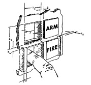
· A channel or cover guard shall be provided when accidental actuation of the control must be prevented. When a cover guard is in the open position, it shall not interfere with operation of the protected device or adjacent controls. (MIL-STD-1472G, 5.1.4.2.1.a(4))
Buttons are generally recommended for discrete activation or for discrete cycling through a limited number of choices. They require a minimum amount of space and a minimum amount of time to operate, but because the setting of the button (i.e., selected or not) may be difficult to determine by position alone, they are not appropriate for discrete control where the function status is determined by position of the button alone (McAnulty, 1995; MIL-STD-1472G; NASA, 1995).
Design guidance to maximize usability is included and summarized in Table 6.4.2.1. Table 6.2.1 provides minimum edge-to-edge spacing requirements between different controls.
Table 6.4.2.1. Design guidance for push buttons. (McAnulty, 1995; RTCA DO-256, Appendix G)
|
|
Push Button |
Push-Pull Button |
|
Minimum Diameter |
0.375 in (9.5 mm) |
0.25 in (6 mm) |
|
Minimum Length |
0.124 in (6.4 mm) |
0.75 in (19 mm) |
|
Minimum Displacement |
0.078 (2 mm) |
0.5 in (13 mm) |
|
Minimum Center-to-Center Spacing |
0.75 in (19mm) horizontally 0.625 in (16 mm) vertically |
1 in (25 mm) |
|
Minimum Resistance |
10 oz (2.8 N) |
10 oz (2.8 N) |
|
Maximum Resistance |
40 oz (11 N) |
64 oz (18 N) |
|
Other Desirable Features |
Provide feedback Concave or friction surface |
Push to activate Increase length if dual use (e.g., if control can be rotated) |
With the exception of push buttons for keyboards, the recommended resistance for push buttons is provided in Table 6.4.2.2.
Table 6.4.2.2. Recommended resistance for push buttons. [MIL-STD-1472G, 5.1.4.2.1.a(5)]
|
|
Single Finger |
Multiple Fingers |
Thumb or Palm |
|
Minimum |
10 oz (2.8N) |
5 oz (1.4N) |
10 oz (2.8N) |
|
Maximum |
40 oz (11N) |
20 oz (5.6N) |
80 oz (23 N) |
6.4.3 Keyboard/Keypad
FAA Regulatory and Guidance Material
· Letter keys on a keypad should be arranged alphabetically or in a QWERTY format. [TSO-C165/RTCA DO-257A, 2.1.5.3]
· If a separate numeric keypad is used, the keys should be arranged in order in a row or in a 3X3 matrix with the zero at the bottom, as shown below. [TSO-C165/RTCA DO-257A, 2.1.5.3]
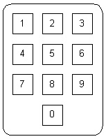

Telephone Style Calculator Style
· If non-alphanumeric special characters or functions are used, dedicated keys should be provided (e.g., space, slash (/), change sign key (+/-), “clear” and “delete,” etc.). [TSO-C165/RTCA DO-257A, 2.1.5.3; RTCA DO-256, 2.1.1]
· Keypads should provide tactile feedback for any key depression. In cases when this is omitted, tactile feedback should be replaced with appropriate visual or other feedback that indicates that the system has received the inputs and is responding as expected. [AC 25.1302-1, 5-4.f(4)]
See also: AMC 25.1302, 5.3.6 which is worded slightly differently.
· Systems that include more than one keyboard should maintain the same configuration for alphanumeric, numeric, and special function keys throughout the system. [MIL-STD-1472G, 5.1.3.2.5]
· A separate numeric keypad should be presented if the user must enter extensive numeric data. (Cardosi and Murphy, 1995)
· Keyboards should be composed of square keys with concave surfaces. (McAnulty, 1995)
· The use of function keys on the keyboard will depend on the system. If function keys are provided, function keys should be clearly labeled to identify the action performed. (Cardosi and Murphy, 1995)
· Non-active keys on the keyboard should not be labeled. (Cardosi and Murphy, 1995)
· The keyboard should be legible and readable in all lighting conditions. (Cardosi and Murphy, 1995)
· Layout of virtual keyboards should be consistent between all applications on a given display.
See also: Chapter 6.4.6 Touch Screens
Keyboard design is important for supporting accurate and efficient data entry. The keyboard design includes characteristics such as the key size, the shape of a key, the spacing between keys, the force needed to press a key, and the feedback provided. Keyboards that are poorly designed can result in arm/muscle fatigue during use.
A logical arrangement and layout of the keys on the keyboard will minimize the potential for error. The keyboard can be arranged in a QWERTY format, so named for the six keys on the top alphabetic line. In the flight deck, pilots can also use an alphabetically arranged keyboard. Consistency in the keyboard layout across flight deck systems will facilitate information entry.
Design guidance to maximize usability is included and summarized in Table 6.4.3.1. Table 6.2.1 provides minimum edge-to-edge spacing requirements between different controls.
Table 6.4.3.1. Design guidance for keyboards. (McAnulty, 1995; RTCA DO-256, Appendix G)
|
|
Keyboard |
|
Minimum Diameter |
0.385 in (10 mm) |
|
Minimum Height |
N/A |
|
Minimum Displacement |
0.05 in (1.3 mm) |
|
Minimum Center-to-Center Spacing |
0.75 in (19 mm) |
|
Setting Separation |
N/A |
|
Minimum Resistance |
0.9 oz (0.25 N) 1.8 oz (0.5 N) preferred |
|
Maximum Resistance |
5.3 oz (1.5N) 2.2 oz (0.6 N) preferred |
|
Movement |
N/A |
|
Other Desirable Features |
Provide auditory or tactile feedback Use telephone layout for digits |
6.4.4 Switches
FAA Regulatory and Guidance Material
· Means must be provided to indicate the current mode of operation, including any armed modes, transitions, and reversions. Selector switch position is not an acceptable means of indication. [14 CFR 25.1329(i)]
See also: 14 CFR 23.1329(h), 27.1329(f), 29.1329(f), which are worded slightly differently; Chapter 4.3.3 Annunciations
Multiple System Configurations
· Where multiple system configurations and more than one sensor input are available for source selection, the switching configuration by annunciation or by selector switch position should be readily visible, readable, and should not be misleading to the pilot using the system. Labels for mode and source selection annunciators should be compatible throughout the cockpit. [AC 23.1311-1C, 18.2]
· Particular attention should be given to the placement of switches or other control devices, relative to one another, so as to minimize the potential for inadvertent incorrect crew action, especially during emergencies or periods of high workload. [AC 25.1309-1A, 8.g(5)]
· The design should provide a way to discourage irreversible errors that have potential safety implications. Acceptable ways to discourage errors include switch guards, interlocks, or multiple confirmation actions. As an example, generator drive controls on many airplanes have guards over the switches to discourage inadvertent actuation, because once the drives are disengaged, they cannot be re-engaged while in flight or with the engine running. An example of multiple confirmations would be the presentation of a temporary flight plan that the flightcrew can review before accepting. [AC 25.1302-1, 5-7.e(1)]
See also: AMC 25.1302, 5.6.5 which is worded slightly differently.
· An indication of control actuation shall be provided (e.g., snap feel, audible click, or associated or integral light). [MIL-STD-1472G, 5.1.4.2.1.c(4)]
· A three-position rocker switch is generally not recommended because the setting may be difficult to read. (McAnulty, 1995)
· Toggle switches should be vertically oriented with OFF in the down position. Horizontal orientation and actuation of toggle switches shall be used only for compatibility with the controlled function or equipment location. [MIL-STD-1472G, 5.1.4.2.1.c(5)]
· If a third position is used on a toggle switch to indicate “off”, the off setting should be in the center position, except where such implementation would compromise performance. In that case, the off setting should be at the bottom. (NASA, 1995)
· Where practicable, rocker switches shall be vertically oriented. Actuation of the upper wing shall turn the equipment or component on, cause the quantity to increase, or cause the equipment of component to move forward, clockwise, to the right or up. Horizontal orientation of rocker switches
shall be employed only for compatibility with the controlled function or equipment location. [MIL-STD-1472G, 5.1.4.2.1.e(5)]
· Rocker switches and toggle switches should not be mixed. (McAnulty, 1995)
· When touch sensitive switches are used, a positive indication of actuation shall be provided, e.g., an integral light within or above the switch being actuated. [MIL-STD-1472G, 5.1.4.2.1.d(5)]
· Legend switches should be distinguishable from legend lights. [MIL-STD-1472G, 5.1.4.2.1.d(5)]
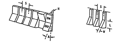
Switches are appropriate when a control has discrete states (e.g., on/off). Switches are often used on annunciator panels, GPS displays, and for master warning/master caution systems. Toggle and rocker switches provide an alternative to push buttons and offer a salient visual indication about their setting. Toggle switches can be used to select among two or three discrete positions, and the setting of the toggle switch is generally obvious. A rocker switch can be used instead of a toggle switch when a control has two discrete positions. A rocker switch is an alternative to a toggle switch when there is not enough space to label the switch positions as it provides a labeling surface. The switch may also be illuminated. However, toggle and rocker switches are susceptible to inadvertent activation (McAnulty, 1995; NASA, 1995).
Examples of switches are shown below. (Images courtesy of MIL-STD-1472G.)
|
Toggle Switch |
|
|
Rocker switch |
|
|
Legend Switch |
|


The introduction of light-emitting diodes (LEDs) to illuminate legend switches as a replacement to incandescent lamps sometimes led to poor readability because the LED did not illuminate the switch uniformly. Rather, the LED created a “hot spot” directly over it and did not effectively illuminate the areas next to the hot spot. Additionally, the text on the legend could not be read off-axis because the LED light was focused directly in front (see http://www.aviationtoday.com/Assets/AVS_0805_Aerospace_Tech.pdf).
Design guidance to maximize usability is included and summarized in Table 6.4.4.1. Table 6.2.1 provides minimum edge-to-edge spacing requirements between different controls.
Table 6.4.4.1. Design guidance for switches. (McAnulty, 1995; RTCA DO-256, Appendix G)
|
|
Toggle Switch |
Rocker Switch |
Legend Switch |
|
Minimum Diameter |
0.125 in – 1 in (3mm – 25 mm) |
0.25 in (6 mm) |
0.75 in (19mm) 0.65 in (15mm) when switch is not depressed below the panel |
|
Minimum Length |
0.5 in – 2 in (13 mm – 51 mm) |
0.5 in (13 mm) |
|
|
Minimum Displacement |
30º for two-position switch; 17º for three-position switch. |
0.125 in (3 mm) in height, 30º minimum angle |
Standard: 0.125” (3 mm) Membrane/Tactile Legend Dome snap-action: 0.03” (7mm) Conductive membrane: 0.2” (5mm) |
|
Minimum Center-to-Center Spacing |
0.5 in (13 mm) for sequential operation 0.75 in (19mm) for random operation |
0.75 in (19 mm) |
|
|
Minimum Resistance |
10 oz (2.8 N) |
10 oz (2.8 N) |
Standard: 10 oz (2.8N) Membrane/Tactile Legend Dome snap-action: 5 oz (1.5N) Conductive membrane: 7 oz (2.0N) |
|
Maximum Resistance |
40 oz (11 N) |
40 oz (2.8 N) |
Standard: 60 oz (16.7N) Membrane/Tactile Legend Dome snap-action: 9 oz (2.5N) Conductive membrane: 11 oz (3.0N) |
|
Other Desirable Features |
Vertical orientation “On” in the up position and “off” in the down position Arm guard to prevent inadvertent activation |
Vertical orientation Upper wing for “on” Higher resistance and arm guard to prevent inadvertent activation |
|
6.4.5 Cursor Control Devices (CCDs)
FAA Regulatory and Guidance Material
· A key benefit of CCDs is their convenience; they are typically located on or close to the pilots' natural hand position, and often accompanied by a hand stabilizer or arm rest. This allows for convenient pilot inputs, particularly since hand and arm motion is minimized due to high device gain. However, CCDs can also lead to control errors, particularly when subject to vibration environments. Also CCD inputs are more likely to go unnoticed by other crew members because pilot inputs are typically accomplished with small finger motions on the CCD. Consider effects on flightcrew coordination in the environment and use conditions of CCDs. [AC 20-175, 3-4.a]
· The graphical user interface (GUI) and control device should be compatible with the airplane system they will control. The hardware and software design assurance levels and tests for the GUI and control device should be commensurate with the level of criticality of the airplane system they will control. [AC 25-11A, 41.b(2)(b).1]
· The CCD design and installation should enable the flightcrew to operate the CCD without exceptional skill during foreseeable flight conditions, both normal and adverse (for example, turbulence and vibrations). Certain selection techniques, such as double or triple clicks, should be avoided. [AC 25-11A, 41.c(1)]
· The safety assessment of the CCD should address reversion to alternate means of control following loss of the CCD. This includes an assessment on the impact of the failure on flightcrew workload. [AC 25-11A, 41.c(2)]
· The functionality of the CCD should be demonstrated with respect to the flightcrew interface considerations outlined below: [AC 25-11A, 41.c(3)]
(a) The ability of the flightcrew to share tasks, following CCD failure, with appropriate workload and efficiency.
(b) The ability of the flightcrew to use the CCD with accuracy and speed of selection required of the related tasks, under foreseeable operating conditions (for example, turbulence, engine imbalance, and vibration).
(c) Satisfactory flightcrew task performance and CCD functionality, whether the CCD is operated with a dominant or non-dominant hand.
(d) Hand stability support position (for example, wrist rest).
(e) Ease of recovery from incorrect use.
· The cursor symbol should be restricted from areas of primary flight information or where occlusion of display information by a cursor could result in misinterpretation by the flightcrew. If a cursor symbol is allowed to enter a critical display information field, it should be demonstrated that the cursor symbol’s presence will not cause interference during any phase of flight or failure condition. [AC 25-11A, 41.d(1)]
See also: AC 20-175, 3-4.e which is worded slightly differently.
· Presentation of the cursor should be clear, unambiguous, and easily detectable in all foreseeable operating conditions. [AC 25-11A, 41.d(2)(a)]
See also: NASA, 1995
· The failure mode of an uncontrollable and distracting display of the cursor should be evaluated. [AC 25-11A, 41.d(2)(b)]
· Because in most applications more than one flightcrew member will be using one cursor, the applicant should establish an acceptable method for handling “dueling cursors” that is compatible
with the overall flight deck philosophy (for example, “last person on display wins”). Acceptable methods should also be established for handling other possible scenarios, including the use of two cursors by two pilots. [AC 25-11A, 41.d(2)(c)]
· If more than one cursor is used on a display system, a means should be provided to distinguish between the cursors. [AC 25-11A, 41.d(2)(d); AC 20-175, 3-4.c]
· Ensure that the cursor symbol is readily discernable from other information, and readily located on the electronic displays. This is particularly important if a cursor symbol is allowed to fade from a display. Some methods to enhance quick location of the cursor are “blooming” or “growing” it to attract the flightcrew’s attention.[AC 20-175, 3-4.b]
· If a cursor is allowed to fade from a display, some means should be employed for the flightcrew to quickly locate it on the display system. [AC 25-11A, 41.d(2)(e)]
· Do not allow the cursor symbol to creep or move without pilot input. Exceptions can include automatic cursor positioning, if it can be shown that it does not result in pilot confusion or unacceptable task completion time. [AC 20-175, 3-4.d]
· In multi-crew aircraft, most applications will allow more than one flightcrew member to use one cursor. Establish an acceptable method for handling simultaneous “dueling cursors” that is compatible with the overall flight deck philosophy. Establish acceptable methods for other possible scenarios, including the use of two cursors by two pilots. [AC 20-175, 3-4.f]
· Labels of graphical controls accessed by a cursor device such as a trackball should be included on the graphical display. When menus lead to additional choices such as submenus, the menu label should provide a reasonable description of the next submenu. [AC 25.1302-1, 5-4.c(2)(a)]
See also: AMC 25.1302, 5.3.3.b which is worded slightly differently; Chapter 6.1 Controls: General
· The same level of performance should be achieved with cursor control devices as with conventional controls. [N 8110.98]
· The CCD should allow for both fast movement and accurate placement. (Smith and Mosier, 1986)
· The cursor should not move beyond the outer boundaries of the screen nor should it disappear from sight. (Ahlstrom and Longo, 2003)
· The cursor symbol should not obstruct any required information.
· The cursor symbol should not be distracting, e.g., when searching for information in a separate location on the display unrelated to the position of cursor symbol. (NASA, 1995, 9.6.3.2.1)
· The shapes used for the cursor symbol should be unique and easily distinguishable from other symbols. The cursor symbol and function should be consistent. Cursor symbols that are different should perform different functions. (NASA, 1995, 9.6.3.2.1)
· Active areas on the display should be positioned so that the pilot can select them without obscuring critical information.
· Active areas on the display (e.g., touch screen controls) should be sized to permit accurate selection with the pointing/cursor-control device in the flight deck environment under all operating conditions (e.g., turbulence). (Chandra et al., 2003)
· The system should use a pointing cursor to indicate the focus of input or attention within a display, and a place holding cursor to indicate the location within a data field where text can be entered. (NASA, 1995, 9.6.3.2.1)
· Pointing cursors should not blink. The size and image quality of the pointing cursor should be consistent across all display locations. (NASA, 1995, 9.6.3.2.1.1)
· The movement of the pointing cursor should appear smooth. Cursors should not move without user input. (NASA, 1995, 9.6.3.2.1.1)
· There should only be one place holding cursor on a display page. (NASA, 1995. 9.6.3.2.1.2)
· If blinking is used to call attention to the place holding cursor, the default blink rate should be 3 Hz. If the blink rate is user-selectable, the blink rate should be between 3 to 5 Hz. (NASA, 1995, 9.6.3.2.1.2)
Cursor Control Devices (CCD; such as a mouse, trackball, joystick, touch pad, or stylus) present unique issues to consider in terms of their usability. First, CCDs are multi-purpose controls so one device may be used to control a wide variety of functions. Consequently, functions that were once immediately accessible using discrete controls (e.g., by turning a single knob) may instead require the flightcrew to step through a series of menus. This sequence of steps will most likely take longer than executing a single action, increasing the time needed to complete a task. Second, it may be difficult to use the CCD with high precision in all operating conditions, e.g., navigating through a series of menus in turbulence or under time pressure. The attention required to locate and access a function with a CCD may increase workload and heads-down time relative to use of a single dedicated control. Finally, it may not be obvious which control function is active or available if labels for CCD controls are presented only on the display screen. It will be important that the pilot be able to quickly identify the active function based on the cursor’s position and what function it will perform. Before implementing CCDs, its use should be compared to conventional controls to understand the potential impact on task performance time and workload. (See AC 20-145 for more information.)
Slow visual feedback may lead to misjudgments in where the cursor is actually placed. A system response within 75 milliseconds is generally acceptable, whereas delays greater than 120 milliseconds may be perceived as being unacceptable (Avery et al., 1999).
One method for showing the location of the cursor when it moves from one flight deck display window into another is to highlight the cursor with a circle.
6.4.6 Touch Screens
FAA Regulatory and Guidance Material
· The location of the pilot’s finger touch, as sensed by the touch screen, should be predictable and obvious. [AC 20-175, 3-5.d]
· If a touch screen’s calibration can drift or degrade, provide touch screen calibration procedures and other maintenance-related items to ensure proper calibration and operation. Include these procedures in the instructions for continued airworthiness, per § 2X.1529. [AC 20-175, 3-5.c]
· Consider integrating an associated support for stabilizing the pilot's hand, and for providing a reference point when positioning fingers, if appropriate. Ensure that touch screens do not result in unacceptable levels of workload, error rates, speed, and accuracy. [AC 20-175, 3-5.a]
· Ensure that touch screens resist scratching, hazing, or other damage that can occur through normal use. Demonstrate that the system will continue to provide acceptable performance after long-term use and exposure to skin oils, perspiration, environmental elements (e.g., sun), impacts (e.g., clipboard), chemical cleaners that might be used in the flight deck, and any liquids that might be brought onboard by flightcrew members (e.g., coffee). [AC 20-175, 3-5.b]
· A touch screen is not appropriate for tasks that require pilots to have their arms raised and unsupported for long periods of time. (Cardosi and Murphy, 1995)
· The touch-sensitive areas should be clearly indicated. (NASA, 1995, 9.3.3.4.7)
· If more than one input device can be used to enter information, the user should not have to switch frequently between the touch screen and other input devices. Switching between the input devices should not impose additional workload. (NASA, 1995, 9.3.3.4.7)
· Soft keys on the touch screen should have a region around them where touches are not recognized to prevent inadvertent activation. (Beringer and Peterson, 1985).
· Feedback should be provided within 100 ms to indicate that a touch has been received (Cardosi and Murphy, 1995; NASA, 1995, 9.3.3.4.7). This feedback can be tactile, auditory or visual in nature.
· A soft key button should activate only when it is pressed and released. If a button is pressed but not released (e.g., a user drags his/her finger away before releasing it), the button should not activate. Additionally, the area where the finger was released should not activate.
· Soft keys displayed on a touch screen should have a minimum size of 22mm across (this recommended size assumes correction to reduce touch bias resulting from parallax errors). (Lewis, 1993; Sears, 1991)
· The angle of the touch screen to the user should be adjustable. If the placement is fixed, the touch screen should be positioned at a 30° angle from horizontal and no greater than 45° from horizontal. Angles greater than 45° may lead to fatigue. (Lewis, 1993)
· To minimize parallax errors, the touch screen should be mounted as close as possible to a position perpendicular to the pilot’s line of sight. (Beringer and Bowman, 1989)
· If the touch screen requires a minimum amount of pressure to register a touch, the pressure should not cause strain during prolonged periods of usage.
· Active areas on the touch screen should be positioned so that the pilot can select them without obscuring critical information.
A touch screen generally operates by registering the position information in response to a finger touch or movement on the device. Advantages to a touch screen are that the relationship between the input action and corresponding output is direct and that all inputs are presented on the display. Touch screen are often used where space is limited. A touch screen may not be appropriate for all tasks or operating environments, however. It will be important to consider the type of touch screen technology, the task requirements, the size of the touch screen and the size of the touch area, and the touch accuracy needed (Cardosi and Murphy, 1995).
There are several touch screen technologies that vary in how they sense and respond to touch.
|
Touch screen technology |
|
|
Resistive |
Resistive touch screens are the most common touch technology. A resistive touch screen is composed of several layers of electrically conductive material. An input is processed when enough pressure is applied so that the layers come into contact with one another, completing a circuit. The amount of pressure needed to register a response will vary from one resistive touch screen to another. |
|
Capacitive |
Capacitive touch screens are coated with a thin transparent conductive material. A “touch” is registered when there is a measurable change in capacitance (e.g., skin contact). No pressure is needed to elicit a response, but input with gloved hands or other styli that is not specifically designed for use with a capacitive touch screen will not be registered as input. |
|
Infrared |
An infrared touch screen uses infrared beams across the active surface of the display to detect input. When an input device, such as a finger, disrupts the beams, a “touch” is registered. The input device does not actually need to come into contact with the touch screen to register a response since the beams of light lie slightly above the screen. However, input can be disrupted by extreme lighting conditions since the display must register any change in the beams of infrared light. |
There are three common strategies for inputting information to a touch screen. A land-on strategy uses the initial touch only for selection. The user can select information by touching that item directly on the screen, and all other contact is not processed until the finger is lifted. Because the system accepts the touch immediately as input, there is no opportunity for the user to verify the entry. Additionally, dragging the finger from one item to another will have no effect. The first-contact strategy is similar to the land-on strategy; the system registers an input when the user touches a selectable item, but “first-contact” also allows the user to select information by dragging the finger from one item to another. In other words, input is not limited to the initial touch. In the last contact or lift-off strategy, the system processes the last selectable item touched when the finger is lifted from the touch screen. Any fields the user may have touched previously is not processed, so the user can verify the correctness of the input before activation. Studies examining human performance with these different input strategies have found a trade-off between speed and accuracy. Entering information with the first-contact strategy was faster than the last-contact strategy, but it was also more error-prone. In fact, the fewest errors were committed using the last-contact strategy than the other two strategies. The appropriate selection strategy for the flight deck environment will depend on the task being performed and the operating conditions (Cardosi and Murphy, 1995; Lewis, 1993; Potter, Weldon, and Shneiderman, 1988).
Text entry via a touch screen keyboard is slower than a standard keyboard (25 words per minute versus 58 words per minute, respectively, using a QWERTY layout), but typing speed can be improved with more experience or more responsive technology. One factor that contributed to the lower typing rate was the inability of the touch screen to process simultaneous multiple inputs (Sears, 1991). The keyboard layout may also facilitate text entry on a touch screen; a comparison of layouts for one-finger typing or stylus entry, as is common with touch screens, indicated that a roughly square (5x5) alphabetic keyboard layout facilitated text entry compared to a conventional QWERTY keyboard layout because the average distance between keys was smaller (Lewis, Kennedy, and LaLomia, 1992 in Lewis, 1993).
In determining whether to use touch screen technology, consider factors such as the speed of the response required (and how quickly a response can be made); the force required for the input, the type of feedback provided, and the risks of inadvertent activation. That is, a pilot may be able to enter information effectively using a touch screen, but if this data entry task requires a high level of precision, head-down time may increase considerably (Cardosi and Murphy, 1995).
There are several issues unique to the design and use of virtual, “soft” controls. Unlike hard controls, soft controls generally do not provide tactile and/or auditory feedback that can be used as a cue to indicate when a function has been activated. Additionally, while hard controls for a display system are generally located in close proximity (e.g., on a dedicated control panel), the location of soft controls may be more varied, and the size of the control constrained by the display real estate. Accessibility of soft controls may also be hindered by display parallax, such that it may be difficult to determine the “active” area (Degani, Palmer, and Bauersfeld, 1992).
Parallax is a difference between the location where users perceive where they can touch and the actual location to touch. Parallax can result in a bias along both the x- and y- axes, and the amount of bias generally varies as a function of the angle of the display. Mounting the touch screen perpendicular to the pilot’s line of sight can minimize touch bias (Beringer and Bowman, 1989).
Several studies have been conducted to examine the appropriate key size for a touch screen. The methodology used for these studies generally require participants to touch some sort of target (e.g., square buttons). The distance between the first touch and the target location can then be measured to determine the key size needed to capture the touches. The collective results of these studies indicate that without correction for touch bias, the minimum key size was approximately 26 mm to achieve a 99% touch accuracy. After correcting for touch bias, the minimum key size was approximately 22 mm for a 99% touch accuracy. The size of the touch screen keys and spacing between keys may need to be increased to accommodate input with gloves (Sears, 1991; Lewis, 1993).